SOHA II
21.03.2012
Alex Cavalli’s SOHA II is a very interesting headphone amplifier. But it has a serious “flaw”: a too low plate voltage and way too low current – only 1mA. The 12AU7 (which is not the most musical tube, btw) needs *at least* 8 mA of current to be reasonably linear and musical.
A 125-130v plate to cathode voltage is needed to get a nice operating point for most tubes. Also, provision for a 20v positive swing is needed, so the B+ will be at least 150V.
The current schematic:

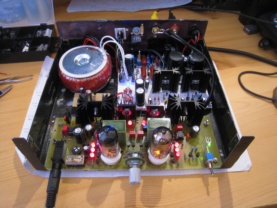
– P1 is the volume control, a 50k stepped attenuator.
– R1 is added to keep the input grid at ground at all times (especially during P1 switching when the grid may become disconnected).
– R2 and R22 are grid stoppers; some tubes, especially the ECC88 family, oscillate when this R is not used. It should be non-inductive; a high quality carbon comp like a Kiwame would be good here.
– The cathodes are loaded with a high quality CCS made of DN2540 depletion mode mosfets. This CCS is *much* better that the original ring-of-two transistors CCS.
– R3 and R4 are there to help stabilize the current mirror and should be 1% matched.
– R5 sets the positive headroom, and it should drop around 18 – 20 volts. Note that there is a 3 volt drop on the current mirror also.
– Q3, Q4 and Q9+Q10 form the current mirror. It is an improved Wilson current mirror, featuring much higher output impedance and PSRR; also, the high voltage Q9 (MPSA92) protects the low voltage/high hFE/low noise BC560C’s from the high voltage.
– R9 and R10 set the feedback ratio.
– C1 is the coupling capacitor. 0.1uF would be large enough to pass bass frequencies, as the buffer’s input impedance is very high. This capacitor should be the highest possible quality – I think I’ll try Mundorf Supreme and russian PIOs here. The only limit is the available space on the PCB…
– The CCS on the buffer is the original ring-of-two BJT’s, because it has a low voltage drop.
* Tube choices
The beauty of Cavalli’s tube input stage is that it accepts a lot of different tubes. Forget about the 12AU7 / ECC82, there are much better tubes out there. Low mu tubes are OK, because we only can use a 30v p-p voltage swing anyway.
* Transistor choices
The output transistor Q6 also influences the sound quality. I rolled several transistors in my previous SOHA II and the differences were important! So, buy different transistors and roll…
* The power supply

1. +150v
I will of course use a high quality stabilized HV supply. I have tried many topologies of HV supplies, and this one is my favorite – a CCS setting the reference voltage for a MOSfet buffer. Each channel will get its own separated power supply capacitor, to minimize crosstalk. The 1 ohm resistor separates the capacitor from the supply, thus the modulated audio currents will only come from the high quality film capacitor.
2. +/-15v
I use a plain symmetric LM317/LM337 adjustable power supply, with high quality ELNA Silmic II capacitors on the output.
I could go even higher on the voltage, for more swing… but at that level the amp would be too loud, anyway, and the opamp can only take 36v rail-to-rail voltage.
3. +12.6v
Another plain regulated LM317 PSU with soft-start.
Work in progress…
Update 07.2015
It turns out this was an unsuccessful project. I couldn’t get it to sound good enough, so I went back to the beautiful, simple and improved original SOHA.

Leave a comment
Comments 0