6AS7G headphone amp
23.09.2014
I’ve heard good things about headphone amps that use the 6AS7G power triode as an output cathode follower buffer. There are a few commercial amps that use this topology (Bottlehead Crack, Darkvoice 336i, Singlepower Extreme). There is a project at HeadWize, too. It is essentially a common-cathode voltage amplifier stage direct coupled to a cathode follower.
I decided to build one myself – if the 6AS7G sounds as good as it looks, it will be a great amp. 🙂
* What kind of a cathode follower should I use?
I have a few options here:
1. Resistor loaded cathode follower
The output impedance of the CF would be Ra/(mu+1)= 300/3 =~ 100 ohm. Ra (the internal resistance) and mu (amplification) should be measured or calculated from the chosen bias point on the plate characteristic curves.
The resistor would dissipate a lot of heat – I want a 80mA bias point, and it will have something like 100 volts across = 8 watt.
2. CSS loaded cathode follower.
The Constant Current Sink has a very high impedance, so the cathode follower will be less loaded and more linear. The CCS limits the maximum current going through the cathode follower – a very good thing when using DC coupling. With the CCS, the cathode follower tube is perfectly safe, even if the preamp tube is accidentally disconnected.
3. Parallel cathode follower
Paralleling two triodes would halve output impedance and slightly reduce noise (by 3 dB), which seems a worthy cause. BUT:
– you need matched/balanced triodes. Balanced 6AS7G are not common…
– you need 2 tubes = double the heater power. One tube burns 2.5A of current, two would need twice that – 5A.
– the lower output impedance means a better damping factor, the membrane movement is better controlled, which can lower the perceived bass deepness.
4. White cathode follower
This would give the lowest output impedance. BUT:
– needs 2 triodes per channel (5A total heater current)
– WCF resistors need to be perfectly tailored to the load and to the triodes, or else it would be suboptimal (=wasted power…). A WCF made of 6AS7G is really not easy to design. Check out John Broskie’s blog for details.
The CCS load was chosen for the cathode follower because of its performance and safety.
* What voltage amplifier topology?
I’ll go with my favorite configuration – a common cathode CCS loaded medium-mu triode stage. Hey, this is the 21st century! 🙂 CCSs were unknown to our grandfathers, or else they would have used them too!
The Constant Current Source is a high quality one, using cascoded depletion mode MOSFETs.
* What tubes should I use?
I have three candidates for the output: RCA 6AS7G, Chatham 6AS7G (this one is really beautiful, with golden grid and copper posts) and a soviet 1970’s Svetlana 6N13S (bought one to compare it to the others).
I intend to roll my best tubes on the input in order to choose the lucky winner. The DC coupling between the stages does NOT facilitate this task, as new settings will have to be used for each tube. An octal input tube would look good on this amp, but I have so many excellent noval ones…
I ended up using the E80CC – truly an impressive and beautiful triode!
* Output coupling capacitors
Hm, not an easy choice. As I only intend to use my 300 ohm Sennheiser HD-650, 47uF would be plenty enough. I really want to avoid electrolytic caps in this amp, so I need a *very* good and not too expensive film cap. Or just a good one, bypassed with an excellent smaller cap.
– Mundorf M-cap: already tried it in the Aikido, not very impressive.
– SCR/Solen: people say they are not that good as coupling caps. Maybe worth trying if bypassed with a very high quality 1uF cap?
– Obbligato gold: these sure look interesting!
– a big dumb electrolytic bypassed by a very high quality film / teflon / paper/oil?
– motor oil caps: don’t have the place for them
– … ?
Finally I went with Mundorf MCap EVO Oil capacitors, bypassed with Audyn True Copper.
* Power supply
It would be cool to use a coke-bottle rectifier! It so happens that i have a few nice NOS 6z3S… 🙂
Is it worth regulating the 2.5Amps of current the 6AS7G needs + 0.3-0.6A for the input tube? Well, I found a small 6.3v 4A switching mode power supply module that is perfect for this job, and it doesn’t need a heatsink like a linear regulator!
High voltage supply is stabilized with a feedback-free MOSFET follower, each channel has its own local reservoir cap and decoupling resistor.
The Tung-Sol 6AS7 datasheet recommends a 30 second cathode warm-up time before applying HV. I do that in ALL of my tube amps, with an automatic 555 timer delay.
Here are the final schematics. F1 … F3 are optional small ferrite beads, you can see them in the amp internal photo. The MosFET gate stopper resistors should be soldered as close to the gate as possible.


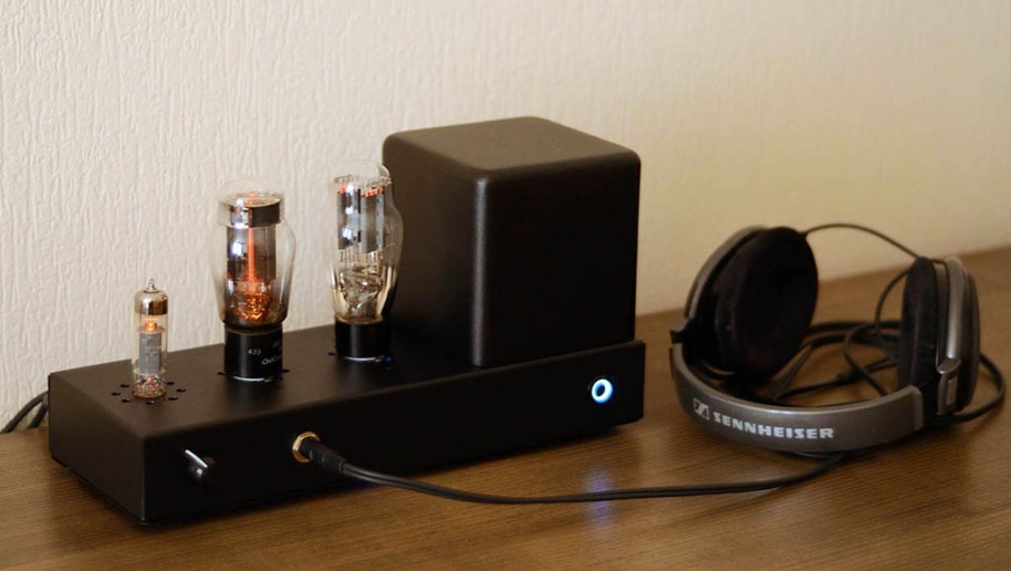
And this is the finished amp:


I am very pleased with how it came out – compact, clean wiring, using some of the best practices around (stabilized HV, CCS loads, HV temporisation, SMPS soft start filaments PSU, tube rectifier…)
How does it sound? Very nice, very detailed and delicate. No surprise, the Chatham 6AS7G is a little better than the others. The Russian copy came last.
